Center-to-vertex distance
r = (√3 / 2)L
r = (√3 / 2)(0.150) = 0.1299 m
The 150 mm cube geometry fixes the gravitational moment arm before component placement is considered.
Independent project · August 2026–Present
Calculated + packaged in CAD · not yet fabricated or tested
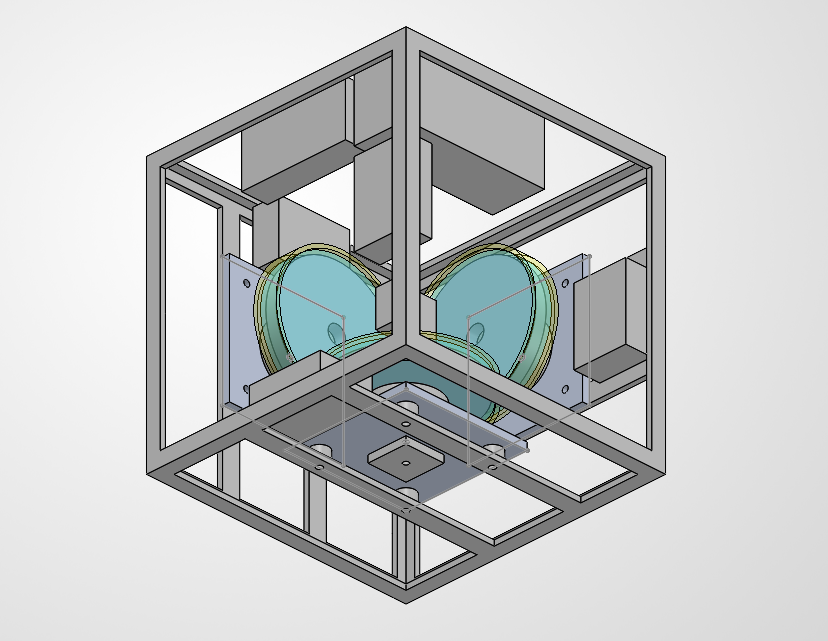
A 150 mm cube designed to balance dynamically on one corner using three mutually perpendicular reaction wheels—the same angular-momentum principle used for spacecraft attitude control.
At a glance
The challenge is not simply spinning three wheels. Cube inertia, gravitational instability, motor torque, wheel momentum capacity, sensor bandwidth, battery mass, and physical packaging all affect whether the same design can balance.
The current result is a requirements-driven architecture and interference-checked SolidWorks assembly. It establishes a buildable direction; it does not yet demonstrate balancing performance.
01 / Rigid-body model
Balancing on a vertex places the center of mass above a point contact. Any small angular error creates gravitational torque that drives the cube farther from equilibrium.
The 150 mm cube geometry fixes the gravitational moment arm before component placement is considered.
For the preliminary 1.65 kg uniform-cube model, the parallel-axis term dominates the inertia about a horizontal axis through the vertex.
At only five degrees of tilt, gravity already consumes most of the preliminary motor's derated torque capability.
This fast open-loop divergence motivated a control-loop target of at least 500 Hz.
Model boundary: These values are preliminary analytical estimates using a uniform 1.65 kg cube. Final mass properties will be exported from the completed assembly and used to update the model before controller tuning.
02 / Actuator sizing
A reaction wheel applies torque to the cube by accelerating in the opposite direction. Motor torque determines the initial correction; wheel angular-momentum capacity limits how much correction remains available before the wheel saturates.
Initial analytical wheel baseline
The current CAD packaging uses smaller Ø70 mm wheel modules. Final wheel inertia and momentum capacity will be recalculated after the wheel geometry and material are frozen.
03 / Requirement decision
At 10°, the preliminary gravitational torque alone is approximately 0.365 N·m—greater than the candidate motor's derated estimate before adding recovery acceleration.
Decision: do not claim 10° recovery.The dynamic estimate produced a worst-loaded-axis requirement of approximately 0.210 N·m.
Decision: continue design at the 5° requirement.The T-Motor MN3508 KV380 remained a preliminary candidate after applying a 20% derating assumption.
Decision: validate on hardware before committing all three axes.04 / Mechanical integration
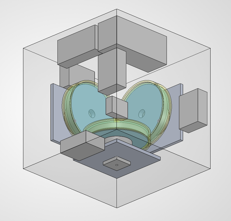
Three perpendicular modules provide torque authority about all three rotational axes while competing for the same central volume.
Wheel envelopes were modeled around each rotating assembly and checked with SolidWorks interference detection, not only by measuring static faces.
Axis and component locations were adjusted until adjacent modules retained approximately 3.16–3.18 mm of clearance without unintended interference.
The IMU was placed near the open center of the cube while the battery, motor controllers, and power hardware were distributed around the mounting structure.
05 / Controls architecture
The baseline power architecture uses a 6S battery with regulated low-voltage rails. A complementary filter is planned for initial testing; an extended Kalman filter remains an optional later refinement rather than a current claim.
06 / Current status
The project has reached a defined architecture and preliminary physical layout. The next phase is to replace assumptions with measured component and system behavior.
Project takeaway
The central design lesson has been traceability: connecting a balance requirement to motor torque, wheel momentum, controller bandwidth, and a CAD layout that can actually be built.